Theoretical Framework
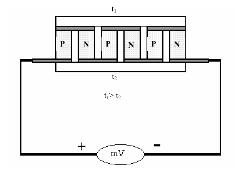
The circuit, in which both heat and electrical factors coexist, is called a thermoelectric circuit, and a system working with this circuit is called a thermoelectric system. Thermoelectric module consists of n and p type materials. Generally, Bi2Te3 is used as n type material and Bi0.1Sb1.9Te3 is used as p type material.
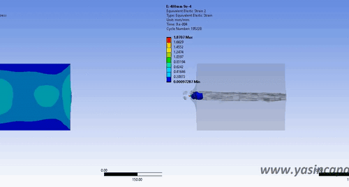
Thermoelectric coolers consist of a large number of thermocouples electrically arranged in series and thermally parallel. Thermoelectric cooler modules are generally produced by placing an equal number of n and p type material pairs (Image 1).
In the building area of the figure, the electric current moves through the lower and upper layers of all n and p type materials and that moves are causing the movement of the temperature. N-type material is an excess of electrons more than needed to create an ideal molecular lattice structure.
P type material is a material that has less electron than necessary to create an ideal molecular lattice structure.
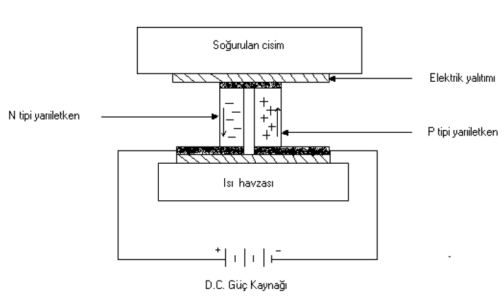
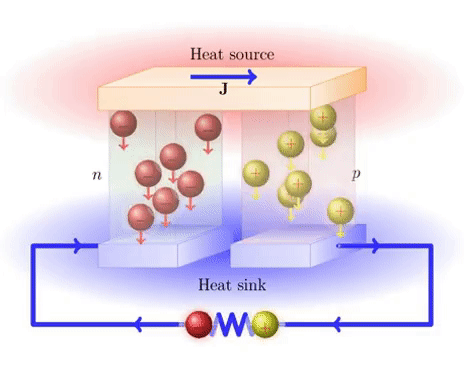
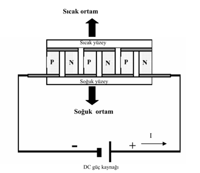
The spaces formed by the excess of electrons in the N type material and the lack of electrons in the p type material are the carriers that move along the thermoelectric module by heat energy. The heat moving at the end of the applied electric current creates heating on one surface and cooling on the other (Image 2). Thermoelectric cooling system operates silently due to the absence of dynamic parts during the cooling period.
Characterizing the quality of thermoelectric materials, it is also named as “material factor”, indicated by Z.
Z= α2 1(1/kp)
In this equation, α is the Seebeck coefficient of the material (Volt/Kelvin)
p is the electrical conductivity of the material (ohms.m)
k is the thermal (thermal) conductivity (W/mK) of the material.
Thermoelectric Effects
Three types of thermoelectric effects occur simultaneously in the circuit by passing electrical current through the circuit created by combining two different semiconductor materials with chemical methods. These three effects are called by the names of the inventors. These are Seebeck, Peltier and Thomson effects.
Seebeck Effect
In the circuit, which is formed by combining two different semiconductor materials in series, the electrical voltage is measured at different temperatures. This voltage is also called “seebeck voltage”. The measured voltage in the circuit is directly proportional to the temperature difference between the surfaces of the materials.
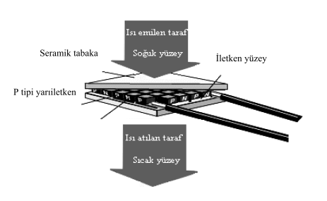
The voltage measured in the circuit created from two different semiconductor materials (Image 3);
V= α ∆T
V: Voltage measured from the circuit (Volts)
∆T= T2–T1
Temperature difference between the surfaces of semiconductor materials (C)
α = α2–α1 is Seebeck coefficient or thermo emf (V/C).
the value of α depends on the properties of the materials that consist the circuit.
For example, α = 40 µV/C for a thermocouple made of copper constantan. In other words, it produces 40 µV for every 10 C temperature difference. Semiconductors are named thermoelectric semiconductors if value of a is bigger than 100 µV/C. For N type semiconductor, α value is negative and for P type semiconductor, α value is positive. The resulting seebeck effect is used as a generator in semiconductors and as a thermocouple or temperature sensor in metals.
Peltier Effect
It was discovered in 1834 that DC current was passing over two different semiconductor materials and creating heat in the direction in which the current was moving by French physicist Jean Charles Athanasa Peltier. This effect is called the Peltier effect. When direct current passes through the circuit formed from two different semiconductor materials, heat is absorbed from the junction point with the Joule heat, while heat is released from the other junction point. The amount of released heat is directly proportional to the passed direct current through the circuit;
QP= π I
QP: Amount of heat transferred per unit of time (W),
I: Passed direct current on circuit (A),
π: Peltier coefficient (V).
π= α T
α: Seebeck coefficient (V/C),
T: Absolute temperature.
QP= α.T.I
Supplied electrical power from outside provides necessary energy for the movement of electrons to within the system. Thus, the electrons transfer heat as they move between varying energy levels, in other words they carry heat.
The number of moving electrons will increase if the electrical power supplied from outside is increased, so the amount of heat transfer between the cold surface and the hot surface will increase. If the current direction is reversed, this process will reverse and replace the hot surface with the cold surface. Due to the Joule and Fourier Effect, the temperature change between the cold surface and the hot surface is not the same. When the circuit becomes stable, the amount of heat that can absorb from the cold surface is found by the equation of QP = α.T.I.
Undesirable heat gains in the opposite direction is found with the following equation.
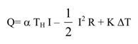
Q: Heat gain per unit of time (W),
TH: Temperature of heat surface (C),
TC: Temperature of cold surface (C),
α= α2-α1, Seebeck coefficient (V/C),
I: Current intensity passing through the circuit (A)
R= R1+R2, Electrical Resistance (ohm),
K= K1+K2, Thermal conductivity (W/C),
∆T= TH-TC, Temperature difference (C).
Thomson Effect
The Thomson effect, which was found in 1856, could be explained as follows. If there is a temperature difference between the ends of a current-carrying conductor, Thomson heat is released in addition to the joule heat according to the current direction. Thomson temperature is directly proportional to current intensity, temperature difference and time. The resulting Thomson heat;
Q T= ι ∆T I
Q T: Thomson heat (W),
∆T: Temperature difference between end of the conductor (C),
I: Current intensity passing through the conductor (A),
ι: Thomson coefficient (V/C).
Fields of Usage in Industry
Apart from electricity production studies in the TEM (thermoelectric module) research, it is mainly used as a refrigerant in industry. It has been found place in many devices that we use in daily life.
Some of examples are given in Table 1.
| Military-Space searches | Electronic circuit cooling, portable cooling, infrared sensors cooling, cooled suit, radio stations |
| Individual | Rest vehicle coolers, car coolers, portable coolers, motorcycle helmet coolers, portable insulin coolers |
| Laboratory and scientific devices | Laboratory cold plate, vision tube cooler, cold room, freezing point reference bath |
| Industrial temperature control | Protecting critical elements from harsh environment conditions, CPU cooling, fixing the ink temperature of printer, |
| Restaurant devices | Chocolate, cream, butter machines |
| Various purpose | Medicine and caravan coolers, for massage and treatment purpose |
Autor: Hakan ÇELİK