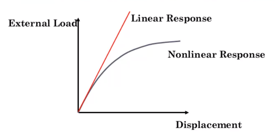
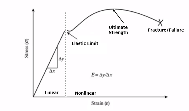
A linear FEA study simulates reality only when a number of restricting conditions are defined. These include that all deflections are so small and, that stress and strains induced by loads remain small enough to let their linear relationship (Hooke’s law) hold.
A linear analysis could miss the target because it fails to detect the geometry’s unstable regions. In these regions, even a small change in load amplitude could lead to considerable different deformations.
Linear finite element method simplifies a lot of things. For instance, the material will never yield resulting in unrealistically high stresses in model. Also, you might not predict failing because nonlinear geometry is not considered.
FEA (Finite Element Analysis) is a simulation of any specific physical matter of fact using a numerical technique called FEM (Finite Element Method).
In Linear Analysis Formulation;
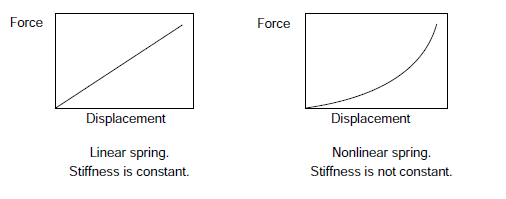
F = k • x
k = stiffness
x = displacement/deflection
F = force
In linear analysis, stiffness has got a constant matrix/coefficient. Therefore force and displacement are directly proportional to each other.
Nonlinear Analysis
Nonlinear effects can originate from geometrical nonlinearity, material nonlinearity and contact. These effects result in a stiffness matrix which is not constant during the load application. This is opposed to the linear analysis, where the stiffness matrix remained constant.
In Nonlinear Analysis Formulation;
F = k • x → F = (k0 + k1• x + k2 • x2 +…) • x
k = stiffness
x = displacement/deflection
F = force
In nonlinear analysis, stiffness matrix/coefficient is updated according to each iteration.
As the stiffness is dependent on the material, which keeps changing according to geometric condition, the initial stiffness matrix can not be used without continually updating it during the course of the analysis.
Numerical solutions of problems involve nonlinearities.
Types of Nonlinearities
Three different nonlinearities are available.
- Geometric Nonlinerity
- Material Nonlinerity
- Contact Nonlinerity
Geometric Nonlinearity
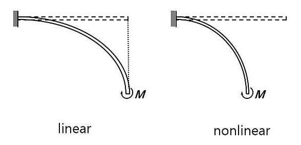
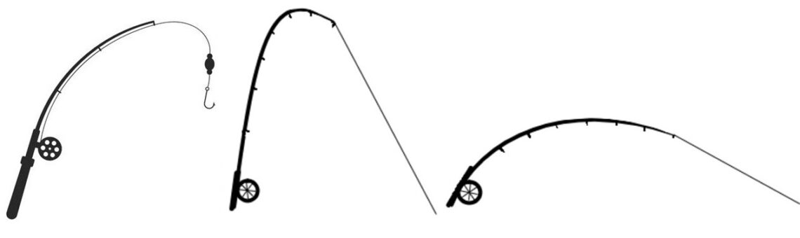
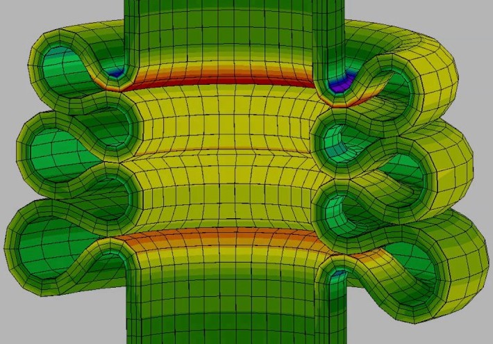
In geometric nonlinearity, changes in geometry as the structure deforms are considered in formulating the constitutive and equilibrium equations. Many engineering applications such as metal forming, medical device and so on analysis require the use of large deformation analysis based on geometric nonlinearity.
Most often, geometrical nonlinearity problems are associated with large displacement effects. Geometrical nonlinearities can also involve small displacements.
Small deformation: Infinitesimal and negligible. 1 meter long bar stretched by 1 mm.
Finite (large) deformation: Large but not infinite and not negligible. 1 meter long bar stretched by 10 mm.
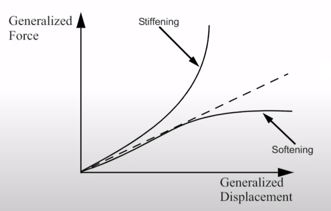
This is referred as geometric nonlinearity If a structure experiences enough large deformation such as changing stiffness of the material. This causes the structure to respond in a stiffened or a softened manner.
Material Nonlinearity
Material nonlinearity involves the nonlinear behaviors of material based on current deformation, temperature, pressure and so on. Some nonlinear material models are large strain, stress-strain relationship, elastoplasticity, plasticity, creep and hyperelasticity.
Contact Nonlinearity
Contact is a type of “changing status”. An abrupt change in stiffness may occur when bodies come into or out of contact with each other. This is a result of the changing nature of the contact between components in the analysis during motion.
In contact nonlinearity, three major areas are taken into account; “Contact Applications“, “Contact Kinematics” and “Contact Algorithms“.
Constraint nonlinearity in a system may occur if kinematic constraints are set in the model. The kinematic degrees-of-freedom of model can be constrained.
Sources:
researchgate.net
homes.civil.aau.dk Magazines