SolidWorks Flow Simulation software is a computational fluid dynamics (CFD) tool that allows designers to calculate and analyse fluid movements, heat transfer, flow loads and fluid forces, which are crucial to the success of their designs. Gas or liquid flows could be analysed and evaluated under real operating conditions.
Engineering Fluid Dynamics (EFD) is a new kind of Computational Fluid Dynamics (CFD) software that allows mechanical engineers to analyze fluid flow and heat transfer applications with powerful, intuitive and accessible 3D tools. Fluid dynamics engineering complies with engineering criteria and objectives; therefore, every product engineer can obtain the technical ideas necessary to answer the questions encountered in the product development process.
Fluid mechanics application allows you to quickly and easily simulate fluid, gas flow, heat transfer and fluid forces, which are crucial for the success of your design, and eliminates the challenges in computational fluid dynamics technique. Flow Simulation lets you determine how a design responds to flow and simulate how liquid, gas, heat, air, and steam move through pipes and nozzles. For engines, the software sets out how fluids will react internally and externally. Besides pressure simulations and thermal simulations, you can optimize your designs for the flow of any fluid based on these tests.
With Flow Simulation;
- Products can be affected by liquid (liquid/gas) or heat transfer can be tested.
- Can improve the cooling process in your designs.
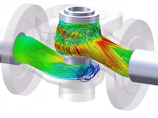
- Pressure drops in valve and regulator can be predicted.
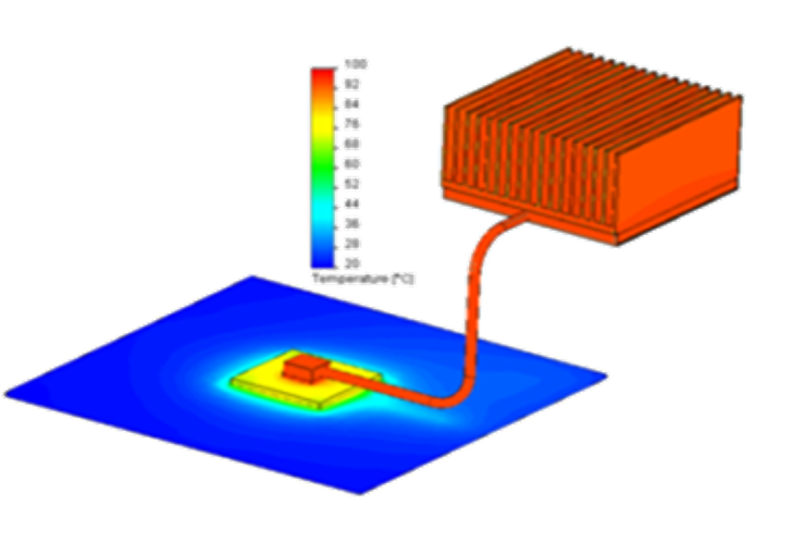
- Can analyse heat receivers, heat pipes or electronic components to detect overheating problems.
- The process of selecting and placing components in your electronic case can be optimized.
- It can be provided that the thermal comfort of the people in the environment where product will be used.
- The performance of lighting products can be tested.
- Can test the risk of contamination in an environment.
It is not easy to reach optimum mesh with standard CFD software package. On the other hand, this step is perhaps one of the most important steps of the analysis process. After all, meshing directly affects the accuracy of the results. An aircraft engine manufacturer spend a very long time to find the best mesh for its designs. Automatic meshers have been available for a long time, but traditional CFD tools still require considerable manual intervention to ensure the quality of voids and overlays, the required curvature, aspect ratio and volume of individual cells. This manual process should be repeated every design change.
For example, designers can analyze the water flow (pressure drop, velocity and turbulence) passing through a valve to optimize it, test the flow in biomedical devices, tubes and narrow channels, or control the air flow around vehicles as well as various other applications. Fluid flow analysis can be used in a wide variety of industries such as automotive, aerospace, defense, life science, machinery and advanced technology. In fact, at some point in every design process are encountered heat or liquid, internal or external and fluid dynamics.
Certificate
Dassault Systèmes provides different certification programs for users according to their using purpose and business. In this context, I have got a great many certificates by Dassault System.
- Certified Professional – SolidWorks Flow Simulation
- Certified Professional – SolidWorks Flow Simulation Electronic Cooling
- Certified Professional – SolidWorks Flow Simulation HVAC
Here are some of my projects:
Electronic Cooling Analyses
Electronic cooling analyzes are carried on these geometries. In these analyzes, some design changes are applied on the system to minimize the heat generated in order to maintain the operating stability of the system and to increase the heat transfer effectively.
Analysis process is completed on this GPU which has got 150W TDP.
- The detail view of graphics processing unit with liquid cooling.
- The detail view of temperature values on the graphics processing unit.
- The detail view of temperature values on the graphics processing chip, memories and mosfets.
- The detail view of temperature values on the solid block of liquid cooling.
- The detail view of temperature values on the top surface of solid block.
- The detail view of liquid’s temperature changing after it touched the graphics processing chip zone.
 The detail view of graphics processing unit with liquid cooling


- Temperature distribution on the system with the default fan position.
- Temperature distribution on the system with the first fan revision position.
- Temperature distribution on the system with the second fan revision position.
- Temperature distribution on the system with the third fan revision position.
 Temperature distribution on the system with the default fan position


Analysis process is completed with a CPU, which has 65W TDP, on this CPU cooler.
- The detail view of boundary conditions on the CPU cooler.
- The detail view of temperature distribution on the CPU cooler.
- The detail view of temperature distribution in the environment of CPU cooler.
 Soğutucu blok üzerinde analiz girdilerinin bazılarının görünümü


Pages: 1 2