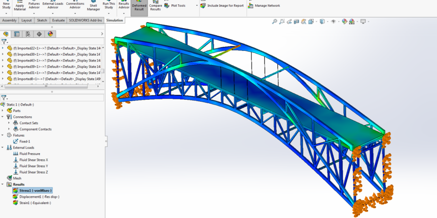
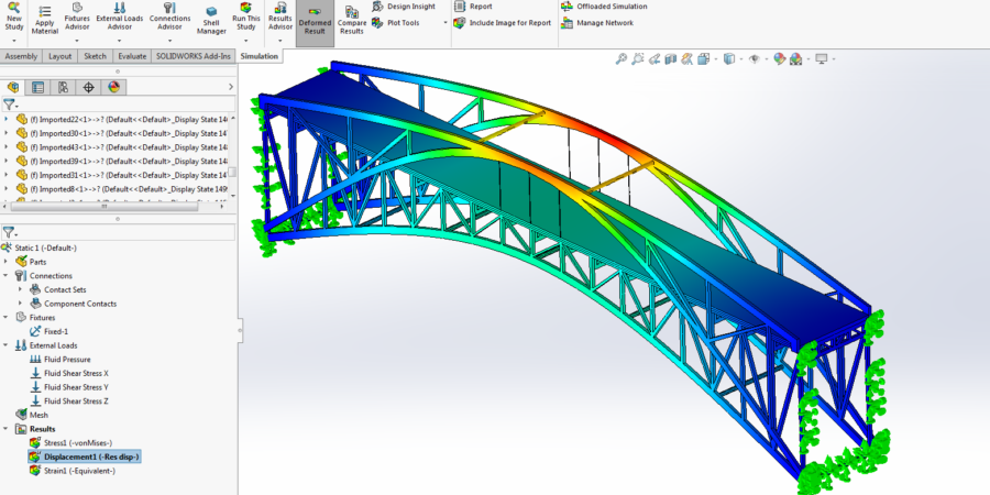
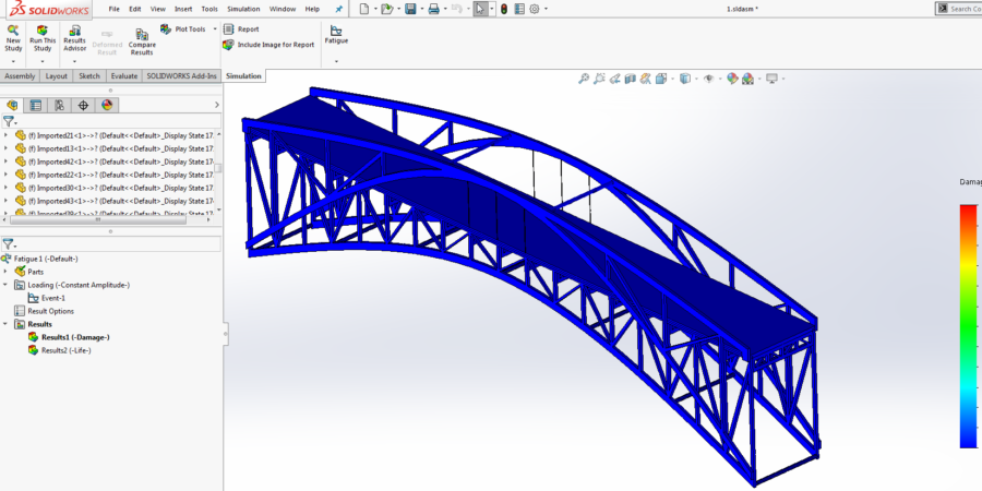
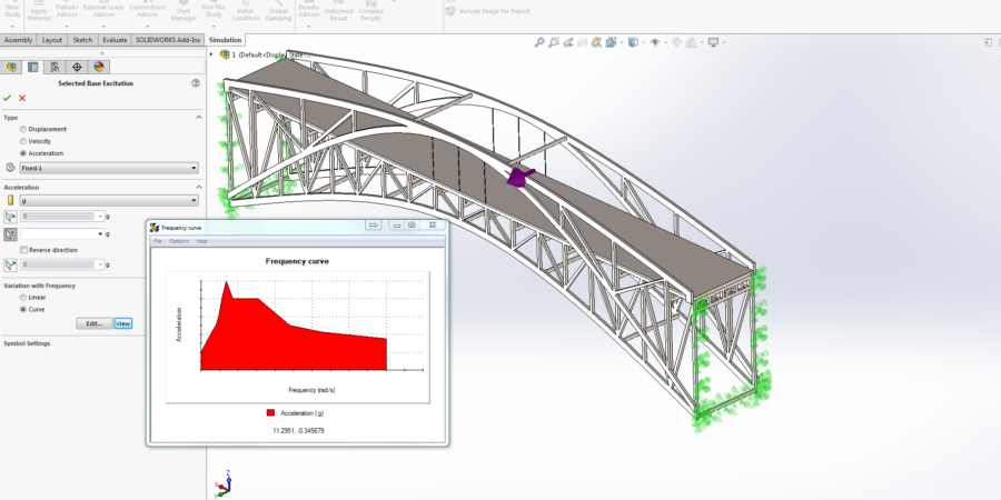
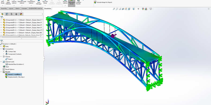
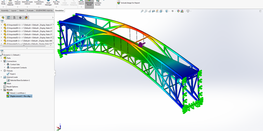
Structural analyses are applied on this bridge. First of all, static boundary conditions then dynamic boundary conditions, which change by time, are applied to work out stress, displacement, strain, safety factor and critical locations on structure. Frequency analysis has done because, before the dynamic analysis, mass participation values and critical frequencies (resonance) of bridge had to be found and considered.
Static, Frequency and Dynamic analyses calculations are applied.
- The result view of bridge after boundary conditions are defined such as contacts, fix, gravity, earthquake load and so on.
- The detail view of where maximum stress is located.
- The detail view of where maximum displacement is located.
- The detail view of frequency analysis.
- Defining the acceleration/frequency curve which is used in dynamic analysis.
- The detail view of where maximum stress is located in dynamic analysis.
- The detail view of where maximum displacement is located in dynamic analysis.
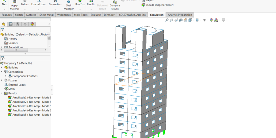
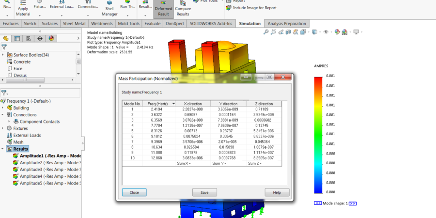
Structural analyses are applied on this building. First of all, static boundary conditions then dynamic boundary conditions, which change by time, are applied to work out stress, displacement, strain, safety factor and critical locations on structure. Frequency analysis has done because, before the dynamic analysis, mass participation values and critical frequencies (resonance) of building had to be found and considered.
Static, Frequency and Dynamic analyses calculations are applied.
- The CAD model of building which is applied structural analysis.
- Mass participation values after frequency analysis.
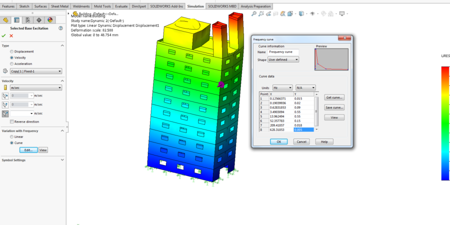
- In first dynamic analysis, boundary conditions are defined in terms of velocity in frequency curve .
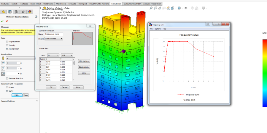
- In second dynamic analysis, boundary conditions are defined in terms of acceleration in frequency curve.
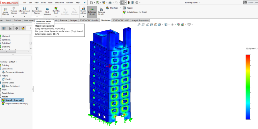
- The detail view of where maximum stress is located in dynamic analysis.
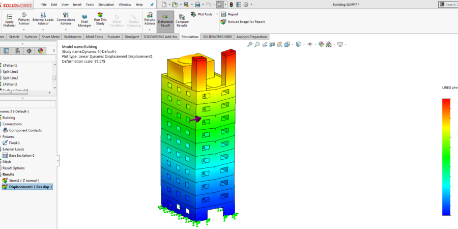
- The detail view of where maximum displacement is located in dynamic analysis.
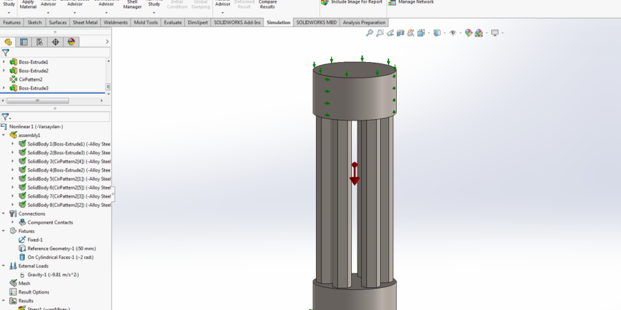
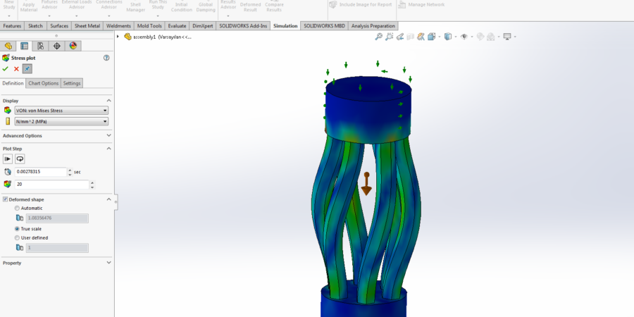
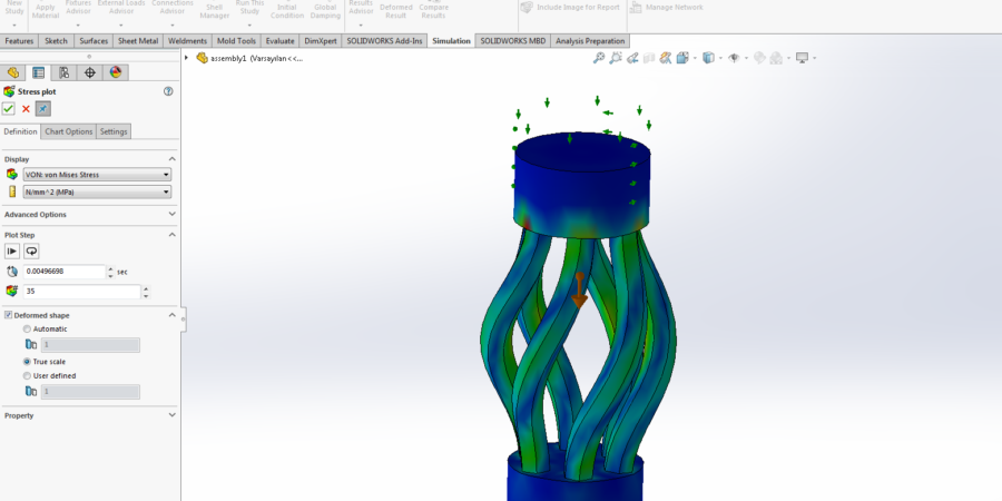
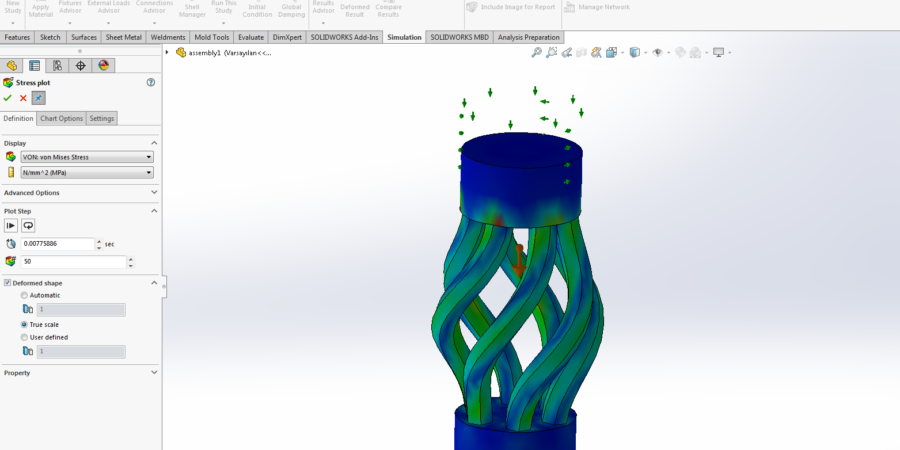
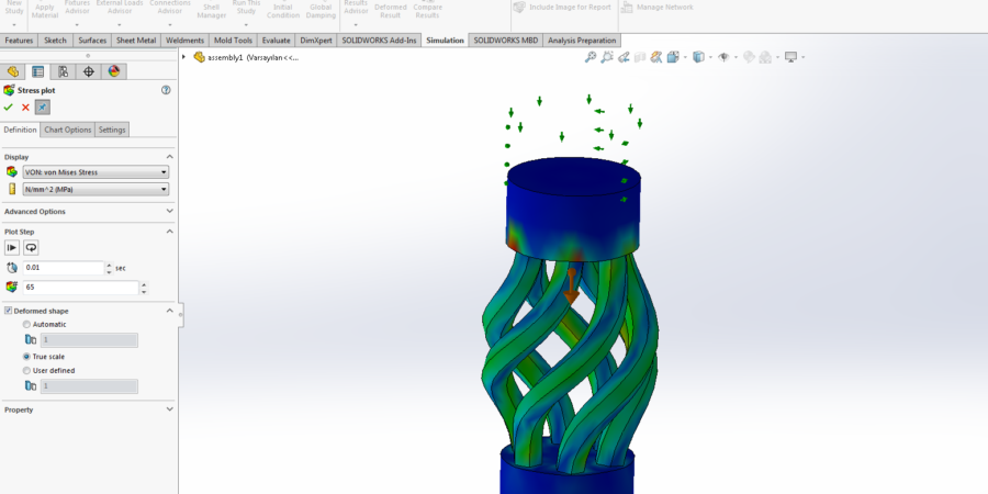
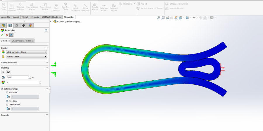
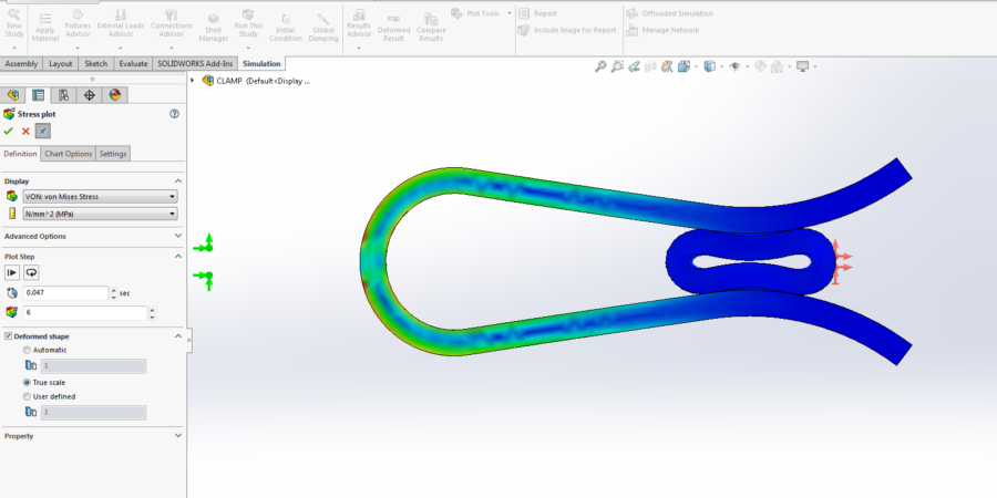
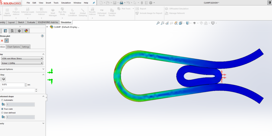
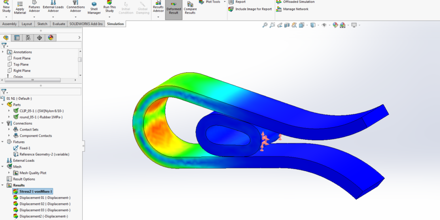
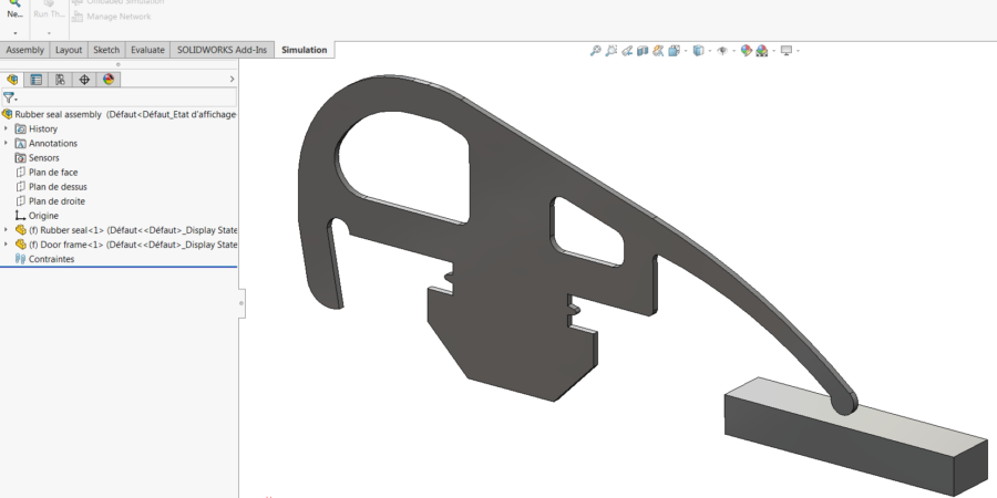
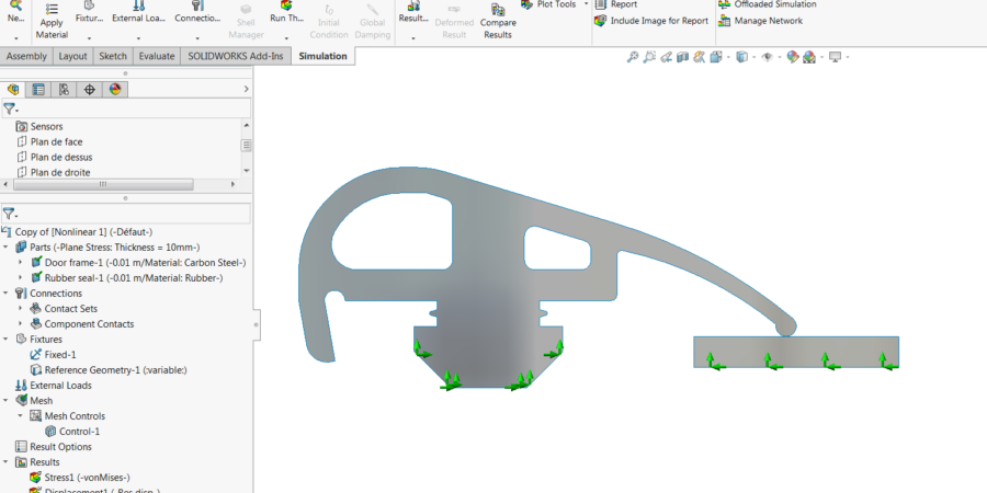
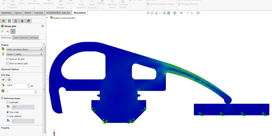
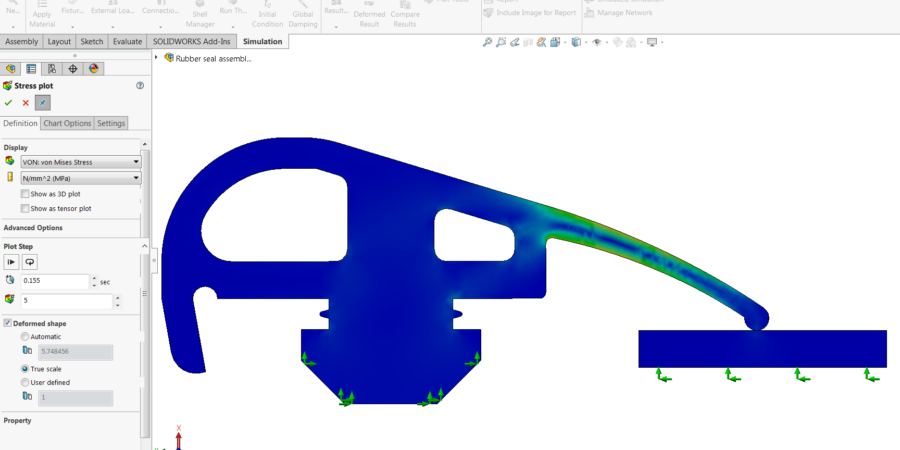
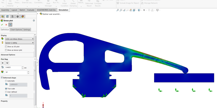
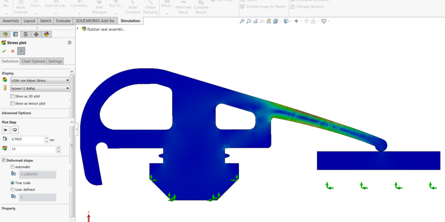
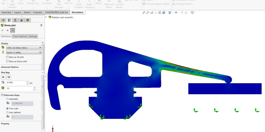
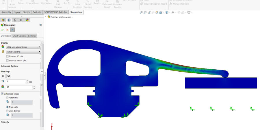
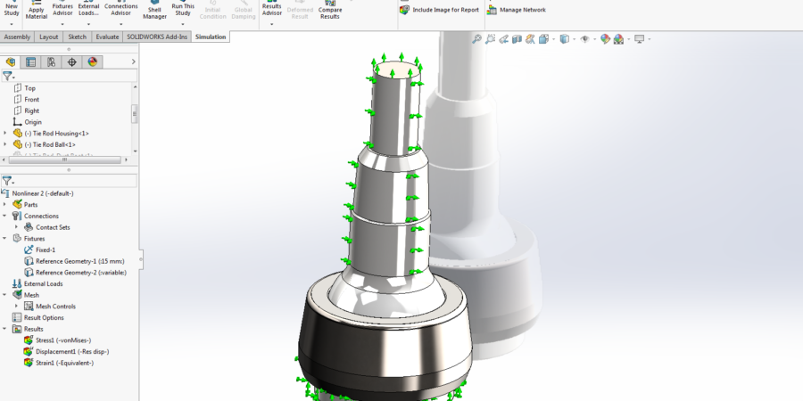
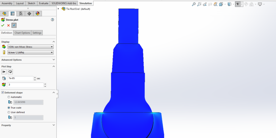
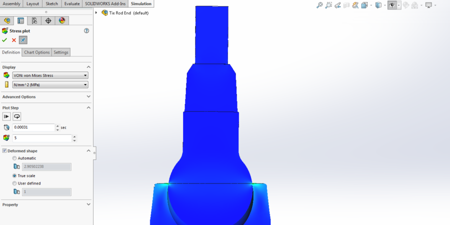
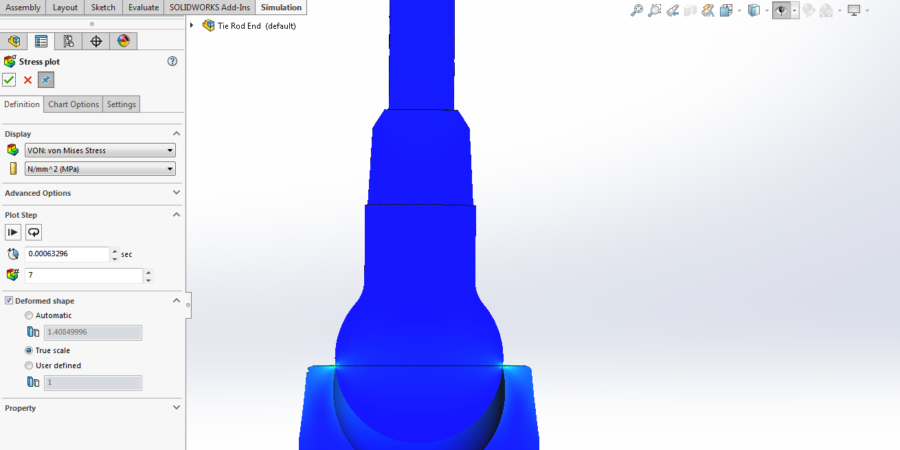
Structural analyses are applied on this geometry. Non-linear boundary conditions, which are not linear, are applied to work out stress, displacement, strain, critical locations and plastic strain ratio on structure.
Non-Linear analysis calculations are applied.
- The CAD model of structure which is applied non-linear analysis.
- The detail view of plastic strain on structure .
Structural analyses are applied on this geometry. Non-linear boundary conditions, which are not linear, are applied to work out stress, displacement, strain, critical locations and plastic strain ratio on structure.
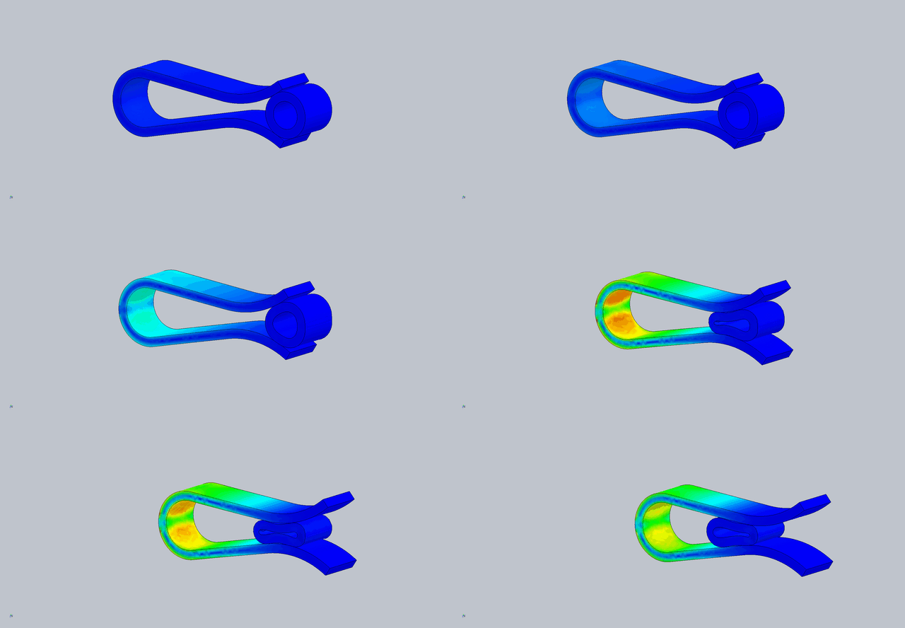
Non-Linear analysis calculations are applied.
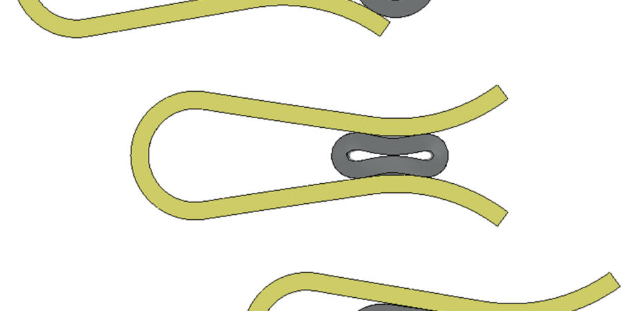
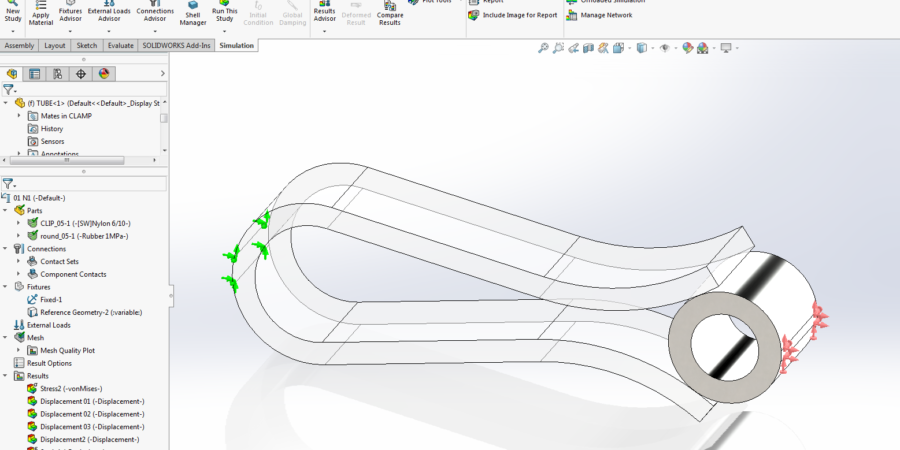
- The CAD model of structure, which is applied non-linear analysis, and the diagram of process.
- The detail view of boundary conditions on structure.
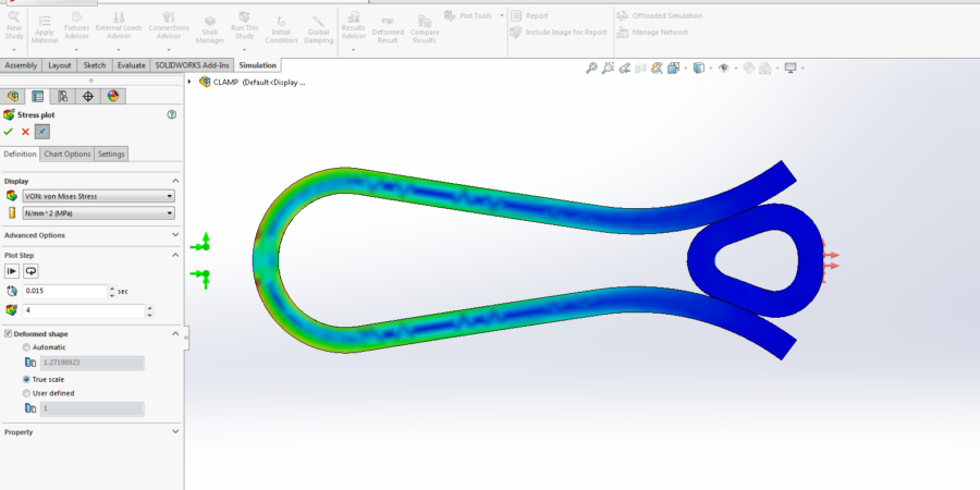
- The detail view of plastic strain on structure.
- The detail view of where maximum stress is located in non-linear analysis.
Structural analyses are applied on this geometry. Non-linear boundary conditions, which are not linear, are applied to work out stress, displacement, strain, critical locations and plastic strain ratio on structure.
Non-Linear analysis calculations are applied.
- The CAD model of structure which is applied non-linear analysis.
- The detail view of boundary conditions on structure.
- The detail view of plastic strain on structure.
Structural analyses are applied on this geometry. Non-linear boundary conditions, which are not linear, are applied to work out stress, displacement, strain, critical locations and plastic strain ratio on structure.
Non-Linear analysis calculations are applied.
- The CAD model of structure, which is applied non-linear analysis, and boundary conditions on structure.
- The detail view of plastic strain on structure.
Structural analyses are applied on this geometry. Non-linear boundary conditions, which are not linear, are applied to work out stress, displacement, strain, critical locations and plastic strain ratio on structure.
Non-Linear analysis calculations are applied.
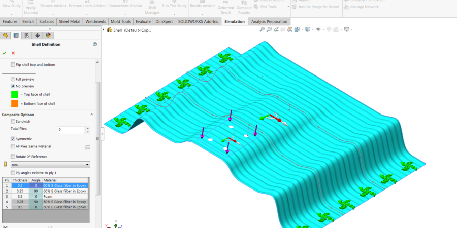
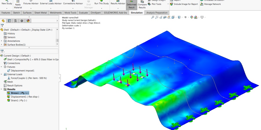
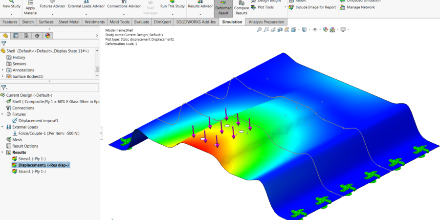
- Defining composite material on structure which is applied non-linear analysis.
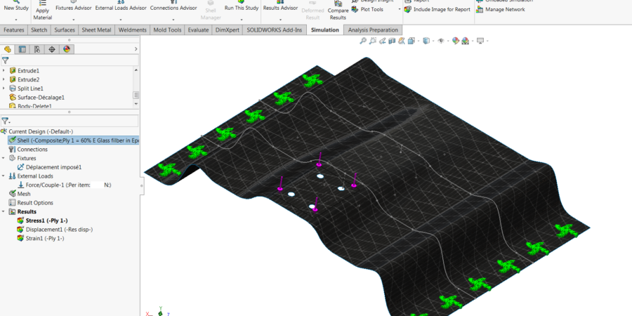
- The detail view of boundary conditions on structure.
- The detail view of where maximum stress is located in non-linear analysis.
- The detail view of where maximum displacement is located in non-linear analysis.
Pages: 1 2
